Yang Xu and Kenny Higa
18 December 2002
Carbon nanotubes, cylinders consisting of graphite sheets, were first discovered in 1991 and were found to possess high stiffness and high strength in a low-density structure[1]. In the emerging field of nanotechnology, these attractive properties have made carbon nanotubes a subject of great interest. They possess either metallic or semiconducting properties, depending on how they are rolled. Nanotubes switches, the subject of our project, have been proposed for use in computers as a smaller replacement for current transistors.
We have adopted a simple model of an electromechanical nanoswitch [2] as seen below, which consists of a carbon nanotube attached to an electrode at one end and suspended over another electrode (actually a graphite plate). A voltage difference is maintained between the nanotube electrode and the plate, which creates a nonuniform charge density distribution along the length of the nanotube. This charge distribution causes the nanotube to deform under the influence of the electric field.
The state of the nanotube, either suspended above the plate or in contact with the plate, indicate the state of the switch.
We run all simulations on a nanotube with a length of 198 Angstroms, a diameter of 13.562 Angstroms, and a chiral angle of 0.5236. The nanotube without defects contains 3240 atoms. This nanotube was generated using an existing program.
Previous work [3] has been done in simulating nanotube bending. We have chosen to study the detailed deformation of a nanotube in our model with the addition of a defect, represented by deletions of atoms in horizontal cylindrical regions perpendicular to the nanotube. In the direction parallel to the graphite plane and perpendicular to the nanotube, this defect appears as a hollow semicircle.
The detailed deformation affects nanotube resistance and the capacitance and threshold voltage of the switch. The threshold voltage, also known as the collapse or pull-in voltage, is the minimum voltage needed to pull the nanotube into contact with the graphite plate below, which represents a change in the state of the switch.
We use a tight-binding hybrid method that combines qualities of both ab initio and molecular dynamics simulations. We build on an earlier simulation [2] in which the nanotube is treated as a completely one-dimensional object. In the quantum mechanical component of our simulation, we solve the Schrodinger equation self-consistently in one-dimension but solve the Poisson equation governing charge density using a two-dimensional finite-element method.
Coulomb's law is used to calculate the force on the nanotube due to the electric field after the charge density per unit length is determined from the quantum mechanical portion of the simulation. We calculate a charge density per unit length rather than per area because the Schrodinger equation is solved in one dimension to save computing time. An analytic solution is known for the force due to the electric field, created by perpendicular parallel plates with different potentials. The effects of the induced electric field are calculated by the method of images.
We later noticed that the force due to the induced field is roughly proportional to that due to the external field. Using this simplifying assumption we could greatly increase the simulation speed since the image charge calculation dominates the force calculations.
Desquesnes, et. al. have shown that van der Waals interactions are significant in this nanoscale system [2] and so we include a 12-6 Lennard-Jones potential to model the interactions between the carbon nanotube and the graphite plane below. Existing code is used to calculate the force per unit length on the nanotube.
The covalent bonds between carbon atoms in the nanotube are represented by a Tersoff potential which has been used successfully to model bond lengths and energies in carbon systems [4]. The Tersoff potential involves a sum over nearest neighbors and includes both a repulsive term and an attractive term, similar to the Morse potential. The attractive term includes a factor that is dependent on the coordination number of each atom. Again, we calculate forces using pre-existing code.
There are two major categories of molecular simulation methods for NT systems: classical molecular dynamics (MD) and ab initio methods. In general, ab initio methods give more accurate results than MD, but they are also much more computationally intensive. A hybrid method, tight-binding molecular dynamics(TBMD)[5], is blend of certain features from both MD and ab initio methods.
Our algorithm, a hybrid, consists of two main parts, a quantum mechanical tight-binding calculation for determining the charge density distribution in the nanotube, and a molecular dynamics part which uses the charge density distribution generated earlier to calculate the electric field. These parts are run alternately, with each part using the data generated by the previous part, until an equilibrium solution is obtained.
This flowchart summarizes the steps of our algorithm:
The quantum mechanical calculations involve two steps: calculating a numerical solution to the one-dimensional time-independent Schrodinger equation that describes the free electrons in the nanotube, and finding a numerical solution to the Poisson equation in the region of the switch. Each step is dependent on the other and so the process is iterated until a reasonably self-consistent potential is obtained. The calculations are initialized by considering only the external field in the initial potential, and the updated potential from the Poisson equation is used on subsequent steps.
The nanotube used in our model may be divided into cross-sectional rings, as highlighted in the image. Under the tight-binding approximation, we only consider interactions between neighboring rings. Since the analytic solution to the Schrodinger equation for the kinetic portion of the Hamiltonian is known, we consider only the potential part of the Hamiltonian, which may be divided into a term due to the external electric field, a term due to electron-electron interactions, and a term due to electron-atom interactions. Under this approximation, the Schrodinger equation may be written as a block-diagonal system. Under a further approximation, the off-diagonal terms are constant [6]. This system is then solved a number of times to obtain discretized approximations to the energy eigenfunctions. The charge density distribution is then generated by using these eigenfunctions and the Fermi distribution.
The Poisson equation is discretized over a rectangluar domain around the nanotube. Centered differencing is used in both the x direction (along the nanotube length) and the z direction (normal to the graphite plate). Written in matrix notation, the differencing equations result in a sparse system which we solve using the sparse matrix capabilities of Matlab. Only the induced potential must be solved numerically since we can obtain an analytical solution of the external potential due to the charged electrodes. For the induced potential, the Laplacian is determined by the charge density in the region within the nanotube, and is zero everywhere else.
The velocity Verlet algorithm forms the basis of the molecular dynamics simulation. Atom velocities are initialized according to a Maxwell-Boltzmann distribution. Then, for a fixed number of iterations, we calculate the forces on the carbon nanotube due to the electric field, the van der Waals interactions with the graphite plate, and the covalent bonds between the carbon atoms in the nanotube. We update the particle positions and velocities according to the Verlet algorithm and repeat.
Below is the initial charge density distribution along the length of the nanotube, as computed by the quantum code. It is compared to a semi-classical solution.
Initial charge density plotThis is a plot of the nanotube before deformation, as viewed from the side. Note: in the following plots, the time scale should be in Angstroms, not nanometers. All times are in seconds.
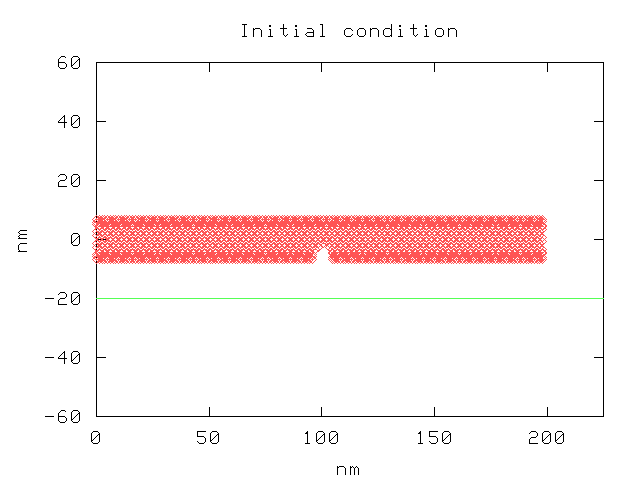
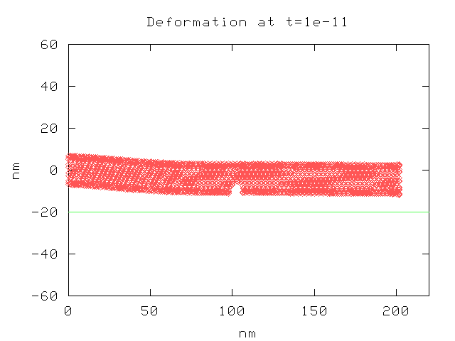
Here is a plot of the nanotube, as viewed from the side. It shows the deformation at 1e-11 seconds under a voltage difference of 5.0 V. The location of the graphite plate is shown by the green line.
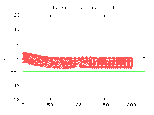
Here is another plot, at a later time step.
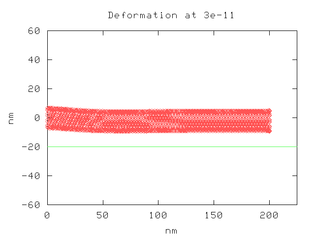
This is a plot of a nanotube without defects, under the same conditions as before, after 3e-11 seconds.
Our code has not been running well for long enough for us to generate sufficient data to draw any real conclusions. It took around ten hours to process the simulation over 6e-11 seconds, and even then the nanotube had not yet made contact with the graphite plate. The timestep is limited by the relatively hard covalent bonding potentials. Our results are only suggestive; however, upon first glance it appears that the nanotubes of this length tend to bend most sharply near their point of attachment and stay fairly straight at longer distances. The deletion of atoms near the center of the nanotube thus seems to have little effect on how the nanotube bends.
Even now, we continue to have problems with automating the hybrid process, which further put limits on how long we could make the simulation runs. We also made the mistake of not dumping output files at some interval; rather, output was only done at the end of a simulation run. Thus, we did not collect enough data to make quantitative comparisons. At the least, we should have run the simulations for the same amount of time, but we were still trying to determine the amount of time necessary for the nanotube to make contact with the graphite surface.
Here's some code (tarball) the might work if you're lucky...
Selected source filesHere's the PowerPoint presentation for our project
PresentationWe are indebted to Yan Li, Zhi Tang, Rui Qiao, and Marc Dequesnes for their assistence and for writing the source code that became the foundation of our project.
[1] Qian, D., Wagner, G. J., Liu, W. K., Yu, M-F., and Ruoff, R. "Mechanics of Carbon Nanotubes". Applied Mechanics Reviews
[2] Dequesnes, M., Rotkin, S. V., and Aluru, N. R. "Calculation of pull-in voltages for carbon-nanotube-based nanoelectromechanical switches", Nanotechnology (13) 120-131, 2002.
[3] Rechefort, A., Avouris, P., Lesage, F., and Salahub, D. "Electrical and mechanical properties of distorted carbon nanotubes." Physical Review B., Vol. 60, No. 19, 13824-13830, 1999.
[4] Brenner, D. W. "Emperical potential for hydrocarbons for use in simulating the chemical vapor deposition of diamond films", Physical Review B. Volume 42, Number 15: 9458-9471, 1990.
[5] Clementi, E. "Ab initio computations in atoms and molecules," (reprinted from IBM Journal of Research and Development 9, 1965), IBM J. Res. Dev., 44(1-2):228-245, 2000.
[6] L. Pietronero, S. Strassler, H. R. Zeller, and M. J. Rice, Phys. Rev. B, (71), 622 1947.