ECE 486 Control Systems
Lecture 1
Welcome! What Is “Control Systems”?
This course is ECE 486, OK, what is it about? It is about a branch of mathematics studying feedback control; it is a means of getting unreliable or unstable components to behave reliably.
Tip: You can check out a survey article by K.J. Aström and P.R. Kumar, Control: a perspective, Automatica, 2014.
Some historical background is also covered in our Text, FPE, Chapter 1. Check them out.
Quick Examples
Control All Around Us
Example 1 The Thermostat
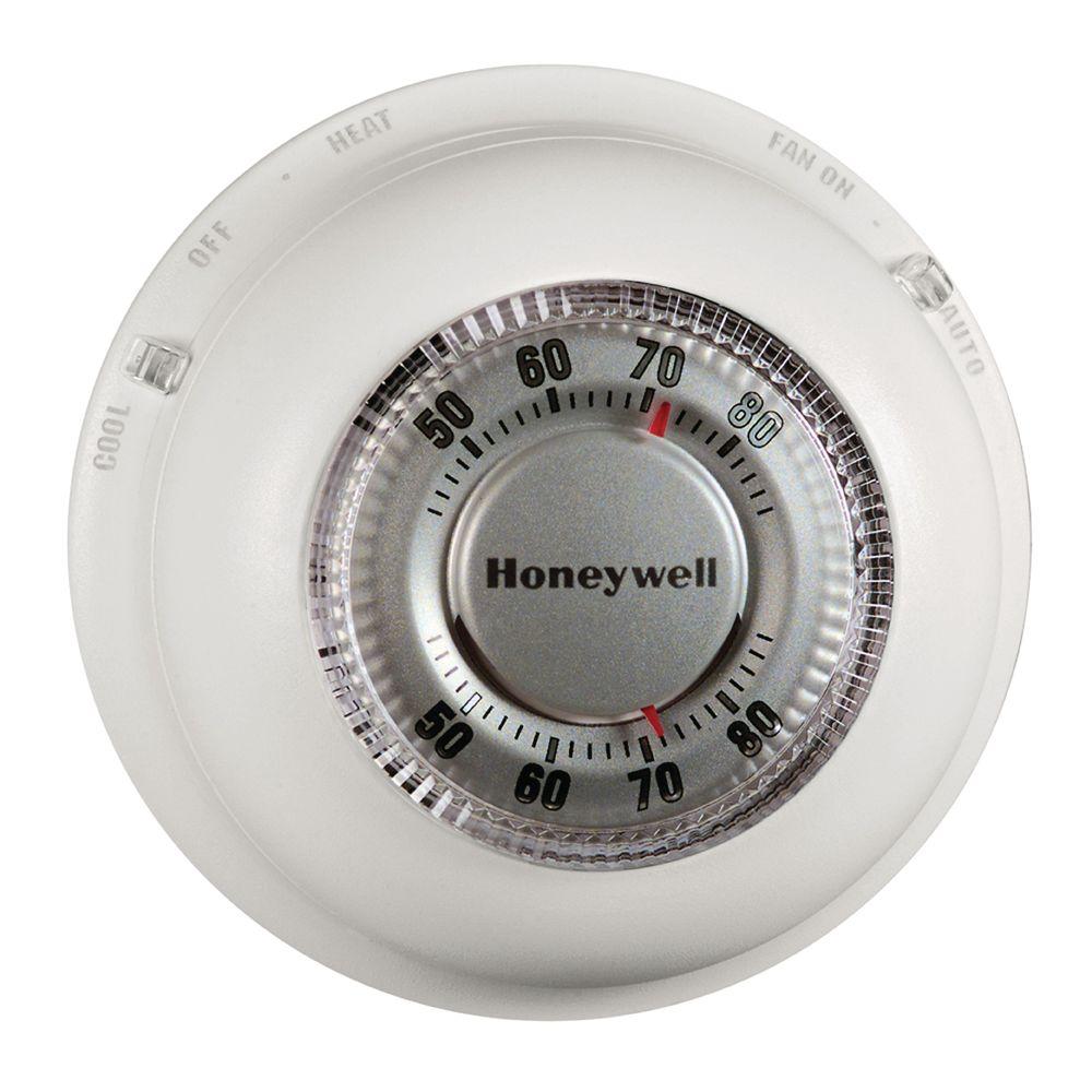
Figure 1: Honeywell T-86 Round

Figure 2: Nest 2nd Gen Learning Thermostat (2014)
The thermostat maintains desired reference temperature despite disturbances (such as doors opening/closing, variations of outside temperature, number of persons in the house, etc.)
Example 2 The Toilet Tank
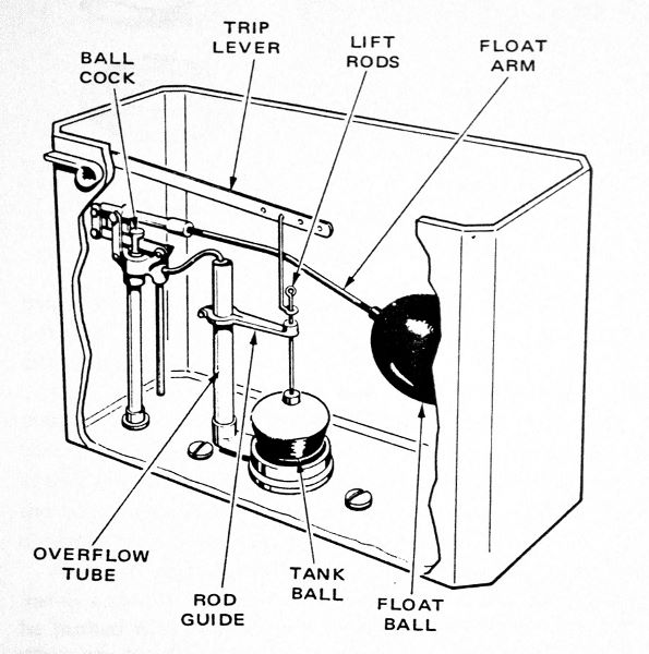
Figure 3: Flush Toilet
The flush toilet employs a control mechanism that ensures that the toilet gets flushed and that the tank is filled to a set reference level. Similar systems are used in other applications where fluid levels need to be regulated.
Components of a Control System
From the above examples, we want to identify some of the components of a control system with the following terminology:
- plant is the system being controlled
- sensors measure the quantity that is subject to control
- actuators act on the plant
- controller processes the sensor signals and drives the actuators
- control law is the rule for mapping sensor signals to actuator signals
Quick History
Feedback Control: Some History
In 1788, James Watt patents the centrifugal governor for controlling the speed of a steam engine. The governor combines sensing, actuation, and control.
The original governor kept the engine running at (more or less) constant speed via what is known today as proportional control. Many improvements were added to the original design.
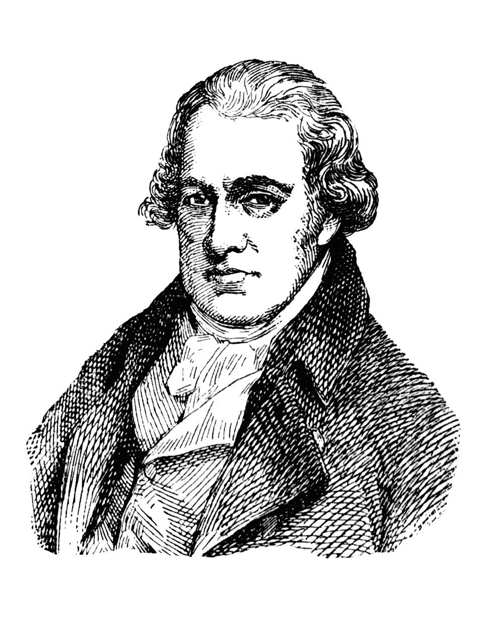
Figure 4: James Watt
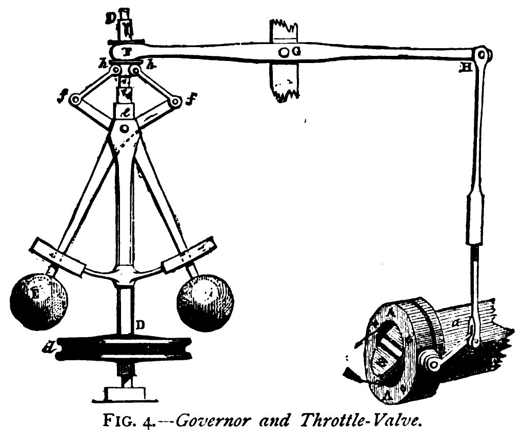
Figure 5: Centrifugal Governor
In 1868, James Clerk Maxwell publishes the first theoretical study of steam engine governors. By that time, there were more than 75,000 governors installed in England.
J.C. Maxwell, On governors, Proc. Royal Society, no. 100, 1868
Stability of the governor is mathematically equivalent to the condition that all the possible roots, and all the possible parts of the impossible roots, of a certain equation shall be negative …
I have not been able completely to determine these conditions for equations of a higher degree than the third; but I hope that the subject will obtain the attention of mathematicians.
The general stability criterion was found in 1876 by Edward John Routh and, in an equivalent form, independently by Adolf Hurwitz in 1895. These are the subjects that we are going to study in Chapter 3, Dynamic Responses.
Ever since the invention of the centrifugal governor, control attracted the interest of engineers, mathematicians, physicists, economists.
In Russia, Ivan Vyshnegradsky developed stability criteria of steam engine governors in 1876, independently of Maxwell. He was a director of St. Petersburg Technological Institute (1875–1878), and ended his career as a Minister of Finance of the Russian Empire (1887–1892).
Some of the earliest textbooks include:
- M. Tolle, Die Regelung der Kraftmaschinen, Berlin, 1905.
- N.E. Joukowski, The Theory of Regulating the Motion of Machines, Moscow, 1909.
Early development of controllers was driven by engineering rather than theory. The effects of integral and derivative action were rediscovered by tinkering.
According to the survey by Aström and Kumar (2014)
- By mid-1930’s, there were more than 600 control companies in the U.S.
- In 1931, Foxboro developed the Stabilog—the first general-purpose proportional-integral-derivative (PID) controller, with adjustable gains from 0.7 to 100
- Between 1925 and 1935, about 75,000 controllers were sold in the U.S.
Other Notable Milestones
In 1905, Orville and Wilbur Wright made the first successful experiment with manned flight. Their main insight was that the airplane itself had to be inherently unstable, which would give the pilot more control and render the overall flying system, (pilot and machine) stable. The first autopilot was developed by Sperry Corp. in 1912.
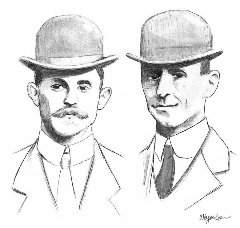
Figure 6: Wright Brothers
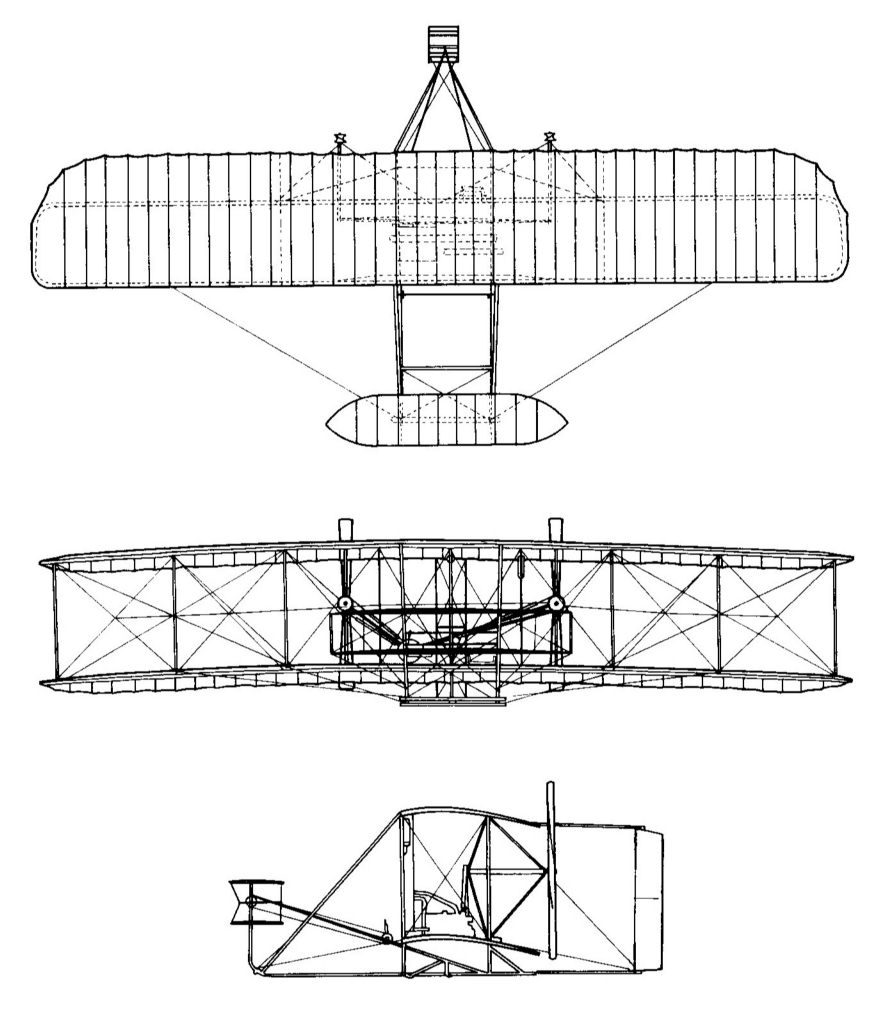
Figure 7: Wright Brothers’ Plane
In 1927, Harold S. Black of Bell Labs developed negative feedback amplifier to reduce signal distortion in long-distance telephony.
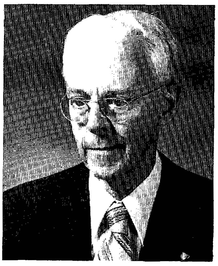
Figure 8: Harold Black
I suddenly realized that if I fed the amplifier output back to the input, in reverse phase, and kept the device from oscillating … I would have exactly what I wanted: a means of canceling out the distortion in the output … By building an amplifier whose gain is deliberately made … higher than necessary and then feeding the output back on the input in such a way as to throw away the excess gain, it had been found possible to effect extraordinary improvement in constancy of amplification and freedom from non-linearity.
It took nine years for Black’s patent to be granted because the patent officers refused to believe that the amplifier could work.
Also at Bell Labs, two other Control engineers developed mathematical theories and furthered practice of feedback control. In 1932, Harry Nyquist studied how sinusoidal signals propagate around the control loop and developed the Nyquist stability criterion. In 1934, Hendrik Bode studied the relationship between attenuation and phase (leading to the concepts of phase and gain margins); identified fundamental limitations of feedback control (Bode’s sensitivity theorem); and developed graphical methods (Bode plots) for designing feedback controllers (loop shaping). These are the subjects that we are going to study in Chapter 6, Frequency Response Design.
After the Second World War, there had been explosive advancement in control systems, some of which were the direct result of the war itself,
- fire control (anti-aircraft, ships, automated aiming …)
- ballistics and guidance systems (autopilot, gyro compass …) … and later on, the Cold War
- unmanned and manned space flight
- control with humans in the loop (Norbert Wiener’s cybernetics)
- communication networks
The aerospace industry was at the forefront of control technology because of extreme demands for safety and performance. It was one of the early adopters of state-space methods, e.g., the use of Kalman filter for navigation in the Apollo Project.
Control—the Hidden Technology
These days, control systems are everywhere,
- home comfort (Roomba, thermostats, smart homes, …)
- communication networks (routing, congestion control, …)
- automotive and aerospace industry (safety-critical systems, autopilots, cruise control, autonomous vehicles, …)
- biology and medicine (cardiac assist devices, anesthesia delivery, systems biology …)
Ever since its birth as an independent discipline, control techniques had evolved a lot as time went by, but the basic analysis and design techniques are still the same as in the early days:
- block diagrams (flow of information)
- Laplace transforms and transfer functions
- graphical techniques: root locus, Bode and Nyquist plots
- state-space methods (linear algebra)
Feedback Control For the Impatient
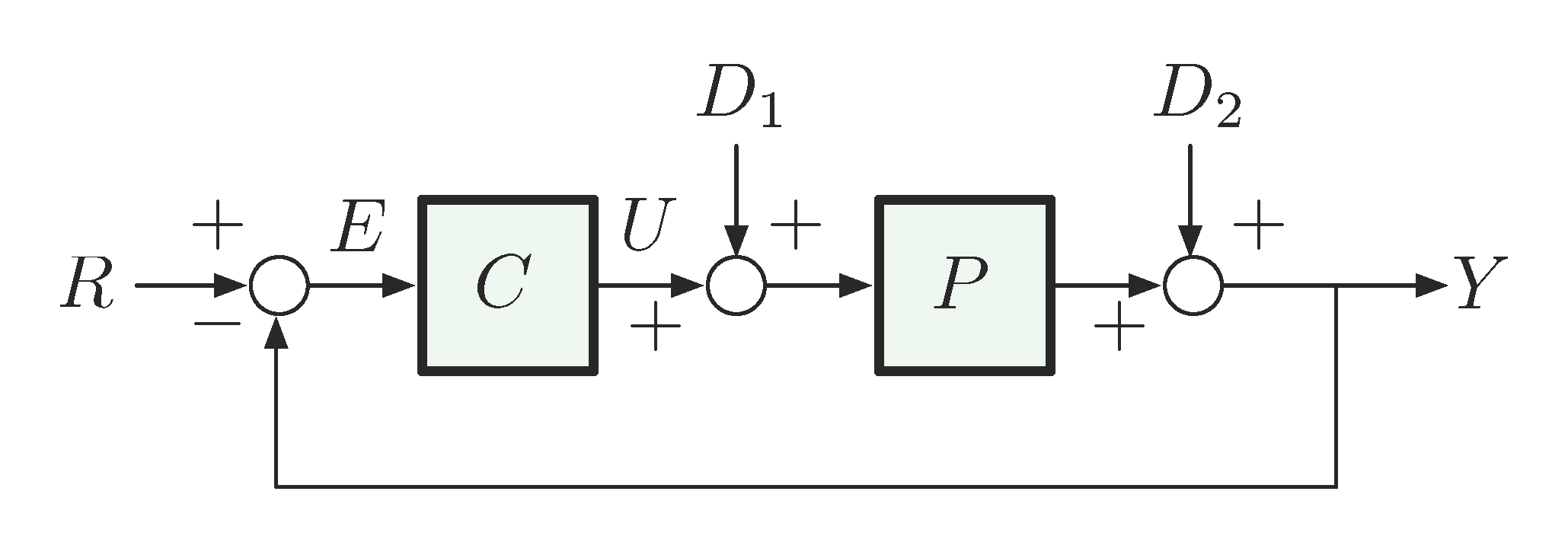
Figure 9: A Basic Control Diagram
In this set-up, we have
- Systems:
- \(C\) – Controller (or compensator)
- \(P\) – Plant. We also have
- Variables:
- \(R\) – Reference
- \(E\) – Error
- \(D_1\) and \(D_2\) – Disturbances
- \(U\) – Control input
- \(Y\) – Output
It is not too difficult to derive the relationship
\begin{align} Y &= D_2 + P(U+D_1), \label{d1_eq1} \\ U &= CE, \label{d1_eq2} \\ E &= R-Y. \label{d1_eq3} \end{align}If we feed Equation \eqref{d1_eq3} back to Equation \eqref{d1_eq2} and similarly further \eqref{d1_eq2} to \eqref{d1_eq1}, we can write down the system output \(Y\) in terms of \(R,D_1,D_2\):
\begin{align*} Y &= D_2 + P(CE+D_1) \hspace{5cm} \mbox{(by plugging \eqref{d1_eq2} to \eqref{d1_eq1})}\\ &= D_2 + P\Big(C(R-Y) + D_1 \Big) \hspace{3.25cm} \mbox{(by \eqref{d1_eq3} to \eqref{d1_eq2})}\\ \tag{4} &= D_2 + PCR - PCY + PD_1. \label{d1_eq4} \end{align*}Therefore based on Equation \eqref{d1_eq4}, with simple algebra, the system output \(Y\) can be solved for as
\begin{align*} Y = \frac{PC}{1+PC}R + \frac{P}{1+PC}D_1 + \frac{1}{1+PC}D_2. \end{align*}Question: Suppose \(C\) is a large positive control gain. What happens as \(C \to \infty\)?
Hint: When \(C \to \infty\),
\begin{align*} \frac{PC}{1+PC}R &\xrightarrow{C \to \infty} R, \hspace{1.75cm} \mbox{(called reference tracking)} \\ \frac{P}{1+PC}D_1 + \frac{1}{1+PC}D_2 &\xrightarrow{C \to \infty} 0. \hspace{2cm}\mbox{(called disturbance rejection)} \end{align*}Then we can conclude from the above two limits when \(C \to \infty\) and Equation \eqref{d1_eq4} that \(Y \to R\), i.e., system output \(Y\) tracks reference \(R\) perfectly when \(C\) approaches infinity.
Next time, we will talk in more details about the mathematical aspects of control. Please start reviewing
- Complex numbers
- Differential equations
- Laplace transforms
from your calculus years.