External Mentors Program
- Program Summary
- Problem Statements
- Donations of Equipment and Money
- Contact and Getting Started
- Ongoing Contact
- Historic Projects
- Course Mechanics Overview
Prof. Carney is always happy to have help or just be given the chance to brag about his students. Contact him anytime.
Program Summary
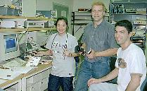
Our mission is to transition seniors in electrical engineering into professional careers. We do this through a one-semester design project that runs from conceptualization through construction and testing. Our top priority is the educational experience of the undergraduate students in our course. We appreciate the intellectual contribution of our partners who come to us from outside the course and hope to encourage participation through this program.
An external mentor may suggest interesting problems and advise teams that select those problems. With graduate Teaching Assistants (TAs) acting as internal managers and mentors, external mentors may select a level of involvement with which they are comfortable. The partnership benefits the students primarily by presenting them with challenges and advice beyond that we can provide internally and by giving them access to potential employers and extra resources such as funds, parts, and technical expertise.
We hope that our external mentors will find the program deeply rewarding. During the course of the semester many of our students grow intellectually at a rate discernible day-to-day. They are smart and humble and hard-working and are excited about making the world just a little bit better. Our undergraduate program is consistently ranked in the top five nationally, usually second. We hope this program will be a good opportunity to interact with potential hires and to expose your organization to a group of soon-to-be world leaders in engineering.
Students are free to propose their own problem or to choose a proposed problem. This freedom is part of our strategy to provide students a chance to work on a project optimally matched to their own strengths and interests. We foster an attitude of ownership of the project by the students and put the rewards and responsibilities of the project in their hands. This is their last and greatest opportunity to excel in our program and find their true potential. As a group, they rise to the occasion.
Problem Statements
External mentors begin their participation by crafting an appropriate problem statement. The course director, Prof. Carney, or the instructor for the current semester is happy to work with prospective mentors to produce a good problem statement. Problem statements must at least be vetted by the instructor. Please see the contact information below.
Projects must have a circuit design and construction component. Most good problem statements are open enough to allow a solution that includes such components. Please try to avoid problem statements that have only software solutions. In the past we have had algorithm oriented projects that included the construction of special digital circuits to handle part of the processing, so a little creative thinking can bring almost any problem into the scope of the course. Additionally, problem statements, like the projects they spawn, must strike an appropriate balance among competing requirements.
- Length
- Statements should be a short paragraph or two.
- Statements might be accompanied by a longer description of background or external resources available.
- Mentoring
- Statements should identify a problem, not the solution.
- A general direction might be indicated, perhaps a strategy, or existing solutions to which alternatives are sought.
- Scope
- Statements should be realistic. This is a one-semester, undergradate project course.
- Inspiring, important problems are more likely to attract student participation.
Good examples
From a member of the faculty:
Every summer, many kids die in overheated cars left in the sun. Fix this problem.
From a member of the faculty:
In my lab I need to monitor changes in the position of a stage with 20nm precision. I have a HeNe laser and that could be part of an optical solution.
From a member of the insurance industry:
There is a signature of impending failure in wires that spark electrical fires. We can provide you with data on this behavior. Build a sensor system to detect impending electrical fires. Parts costs must be under $100.
From a campus project:
We are building an all electric car as part of a large project. We need a system to regulate the output of regenerative braking and integrate with a battery charging system that includes other sources (solar and wall power). We have specific tolerances for ripple and bounce. A primary challenge is protection of the generators. Detailed requirements are given in the available background document as well as a description of the larger project. Finances for parts and supplies are available up to $2000.
Bad examples
From a hypothetical member of the faculty (specifying the solution):
Every summer, many kids die in overheated cars left in the sun. Connect a temp sensor to a voltage comparitor and a latch. When the latch goes high have the bluetooth module I will give you send a message to the OnStar system in the car asking them to check for passengers.
From a hypothetical member of the faculty version 2 (unrealistic):
Every summer, many kids die in overheated cars left in the sun. Build a machine to teleport endangered children to safety.
From a hypothetical member of the insurance industry (specifying the solution and too easy):
There is a signature of impending failure in wires that spark electrical fires. We can provide you with data on this behavior. Use a current sensor, an ACS714 built into the circuit shown in the attached diagram, to feed the A/D converter I will give you. Then write code to do matched filtering to select dangerous signals.
From a hypothetical campus project (solution given):
We are building an all electric car as part of a large project. We have designed a system to regulate the output of regenerative braking and integrate with a battery charging system that includes other sources (solar and wall power). We need you to build the design. Finances for parts and supplies are available up to $2000.
From a hypothetical campus project (unrealist):
We are building an all electric car as part of a large project. We need a system to regulate the output of regenerative braking and integrate with a battery charging system that includes other sources (solar and wall power). We have specific tolerances for ripple and bounce. A primary challenge is protection of the generators. Detailed requirements are given in the available background document as well as a full description of the project. The circuits must be 95% efficient and we have no budget.
Presenting in person
Every semester we have several external mentors come talk to the class during the first two lectures (the first two Wednesday afternoons of the semester). We ask that the presenters be brief (5 minutes) and suggest that they stay for questions after the end of the lecture. We can provide a projector and internet access to aid in the presentation. We are very happy to have personal appearances.
Donations of Equipment and Money
(Contact)
We do not require a fee to participate in the senior design process. We consider the contribution of time and intellectual effort to be significant. A good idea brought to us by an external mentor is a benefit for the students. However, our budget is limited and expensive projects simply cannot be completed without additional financial or material support. Sometimes external mentors are able to make available special equipment or supply parts, sometimes they are able to make cash donations.
In addition to the marginal costs of a project, please also keep in mind the cost of the support network ( teaching assistants, instructors, lab managers, etc) as well as the capital investment in equipment in the department in the millions of dollars. We encourage companies interested in mentoring to consider making a contribution to the department to help defray these costs. Gift money left over from a given grant will be placed into the class general fund which is used for parts for all students. We also encourage the donation of equipment and parts. Typical donations from large companies have come in $5000 increments and donations from small, local businesses have been in $1000 increments. These are suggested starting points and any support at all is appreciated.
We are always happy to work with schools, nonprofit organizations and individuals on good works projects to improve education, overcome handicaps, or contribute to the life of the community. We understand that these organizations face even greater financial hurdles than we. Indeed, the flow of material on these types of projects is usually out of the class as we can often provide the completed project prototypes to these organizations free-of-charge. Of course, this sort of activity is also made possible by the support of other generous donors.
Please also realize that this is an undergraduate class. We believe that what we do is important and that the educational mission benefits our students, their future employers, our society, and the world. We hope that our partners also benefit by contact with these extraodinary young people and that they believe in the mission. Sometimes projects are successful in that a product or result is delivered as hoped at the start. Sometimes everyone gets experience. We cannot promise that external mentors or benefactors will benefit directly. If you have a project that is well suited to an academic research setting and that must come through with certain deliverables, we would be happy to facilitate contact with the appropriate faculty to form a sponsored research agreement.
Contact and Getting Started
Contact Professor Carney by email at carney@illinois.edu. Contact is welcome anytime, though ideally enough time before the start of the semester will be allowed to pass a problem statement back and forth a couple of times. This usually means two or three weeks before the start of the semester. The class meets the first Wednesday of the semester. The academic calendar is available here. Early contact never hurts. For maximum efficiency, please email Prof. Carney with the following information:- Name of company (if applicable)
- Name of person to contact
- Contact address, email, and phone
- Project title
- Brief problem statement (<200 words)
- Whether you want to:
- Provide funds
- Furnish parts or equipment access
- Provide mentoring without parts or funds
- If you would provide active mentoring for the students, please include name, email, phone, and address
- Advice to the instructor for selecting students (<150 words)
Ongoing contact
If your problem is taken up, we will work with you to set up a contact schedule that you are comfortable with. If you have time to very actively mentor the students, a weekly meeting by email, phone or even in person may be appropriate. If you are busy or such regular contact just isn't called for, less frequent meetings or just regular updates may be arranged. Regardless of external mentor participation level, every group will be assigned an internal mentor (a TA) who will ensure that the academic aims of the course are being met. We encourage mentors to attend demonstrations and presentations at the end of the semester if reasonably possible.
If your problem is not taken up one semester, we can carry it over to the next if you like. We can also work with you to more carefully state and scope the problem to attract participation. Our students are deeply intellectually ambitious. They are often up for changing the world.
Historic projects
The course has used an online project management and archiving system since 1999.
Hall of Fame
Each semester, we give out awards to students that have performed exceptionally well. A list if these award winners and links to their project details are available in the "Hall of Fame."
Search all Student Projects
The Senior Design class of the ECE department has all of its projects posted online. The database includes details such as proposals, presentation slides, final papers, and student resumes. With 100 students and 40 projects in a typical semester, it has become a worthwhile recruiting tool.
Course Mechanics Overview
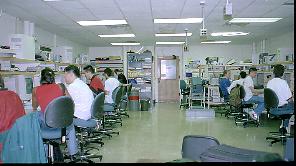
The Senior Projects Class (ECE445) is a 2 hour required laboratory class for electrical engineers where the students 'engineer' a project. We typically have 100 students (40 projects) per term.
A major course objective is to offer the students a guided design experience which involves all the issues of design, assembly, and test of hardware. We work to develop written communication skills through a written proposal, design schematics, and a final report. Oral skills are developed through weekly meetings with TAs, the informal design review, an oral demonstration, and a formal presentation. Up until this point in their. In addition we teach the students to follow a schedule, to keep track of cost, and to deliver on time.
Schedule
The semester begins over the 1st 10 days on 'identifying a project' and picking a partner (or 2 in some cases). A week later, the project 'PROPOSAL' is due and 10 days later, an informal design review is held for each project with the course Director, Graduate Student Teaching Assistant, and another student team as a PEER reviewer. Each team must peer review another. Following this, the students enter the assembly, build, and test phase of the project (9-10 weeks). The last week of the semester involves a 'DEMONSTRATION' and 'PRESENTATION' (30 minutes each), along with a 'FINAL REPORT', which will be submitted electronically. As part of the exercise, students are encouraged to be ambitious, but for overly ambitious projects we bracket a section to be graded.
Resources
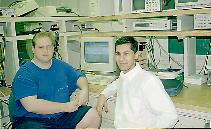
Our resources include people and equipment. In addition to myself, we have 5 graduate students with varied backgrounds who each take on an average of 12-15 projects for weekly team meetings. The graduate students gain management experience in this role. We have 90 faculty members in ECE, but a dedicated set of 8-10 advisors are identified for the students. These advisors act as discipline specific mentors or advisors, especially early in the project formation when students are focusing on the specific problem formulation. We have a dedicated laboratory which they have access to 24 hours a day. The environment is informal so the students feel comfortable as they put in long hours on their projects. We have an electronics shop which has been stocked with many parts from generous donors. We have an electronic method for the students to order parts from the shop. We have a budget of ~$40 per project for those parts not available in the shop which can be ordered from our own store or business office located in Everitt Lab.
On-line Projects Database
Details about the course can be found on the home page. All projects are posted on-line in the projects database.
Selection of Projects
How do the students pick projects? The first two class meetings, we overwhelm the students with our ideas. We invite the advising faculty to provide ideas in power, microprocessors, biomems, remote sensing, and so on. In fact, about 1/3 of the projects are actually implemented in research laboratories in microelectronics laboratory, biomems laboratory, or other ECE research laboratories. The students are told to choose a project by day 10, or one will be provided to them. They all come up with one of their own, but with lots of advice on how to follow the project requirements.
Motivation
Motivation? My motivation as the course director is to provide the greatest opportunity for the students and to give them a practical experience. The students become motivated simply by being linked to a real customer. I also believe this is a great way for industrial sponsors to work with students who will be graduating.
The interaction offers an experience which may lead to employment. The company sponsor may actually get some real problems solved! Institutions who have in-house component availability and can supply those components to the students are most welcomed. The course is a real fire drill from the standpoint that all activities must be completed in a semester and parts accessibility is a real key to project success. We have a firm schedule and we stick to it. With the gift funds, we can order parts which are in stock with suppliers and use expedient delivery services when necessary.
Deliverables
The project product in this case is the final report. Final reports for the class will be made available electronically to all, so confidentiality is not normally part of the deal. The reports are used as an archive for the following class to grow from and for industry recruiters to search. The final reports can lack specific information, and not be published if that is desired on the part of a project sponsor.
Wrap-up
As you may well imagine, the process we have set up to manage and funnel resources directly to students is most efficient . The gift funds for this activity are not burdened by the University. A project will be managed just like the rest of the projects in the class. Sponsors are invited to participate in reviews, as they wish, and to make input during those reviews. Review dates are posted on our calendar each term, and specific team review times are formulated and available at least 2 days before the actual reviews. A project offered does not guarantee it will be performed a given semester as we still leave it to the students to select a project they are interested in. In this case, no funds will be spent or redirected, but the project will be offered the following term, unless otherwise specified or modified by the sponsor.
Thank you for your interest and support!
Sincerely,
Prof. P Scott Carney and Prof. Gary R. Swenson