Project
| # | Title | Team Members | TA | Documents | Sponsor |
|---|---|---|---|---|---|
| 30 | Transverse String Organ |
Ash Huang Eddy Perez Kellen Sakaitani |
Shengyan Liu | design_document1.pdf final_paper1.pdf other1.pdf presentation1.pptx proposal1.pdf |
|
| # Title: Transverse String Organ Team Members: - Eddy Perez (ekperez2) - Ash Huang (akhuang3) - Kellen Sakaitani (kellens4) # Problem Electric guitar feedback is traditionally produced by amplifying the signal from the instrument loud enough that the energy stored as sound can induce a sustained feedback loop in the guitar string. Products such as the EBow take this concept and remove the inefficiency of energy transmission through sound by instead sending the amplified signal through magnetic driver coils (think of speaker drivers) directly into the string. Products such as this implement harmonic controls through analog filters in the signal chain, causing the string to resonate in higher octaves. Techniques such as this create a unique timbre from this instrument which can be finely controlled by the player and the electronics of the instrument. This unique timbre is restricted to a small number of notes (1-6 strings) at any given time and can only be utilized musicians who are trained on guitar. # Solution Our team would like to bypass these restrictions by making a harp or organ-like instrument with one feedback system per string. This instrument would ideally consist of twelve strings representing the chromatic scale in either the first or second musical octave. Our instrument would be controlled over a MIDI interface, allowing it to generalize to a broad range of musical controllers for those with backgrounds in various instruments. The instrument would be comprised of two main systems: the Master Board and the individual DSP Feedback Systems. The Master Board will act as the host of the system; it will listen to a MIDI signal through the UART peripheral of an STM microcontroller, and translate specific MIDI commands to an I2C bus, where this system would act as the master. This board will also include a 3.3V DC/DC regulator to power the MCUs of the other boards of the system. On the slave side of the I2C bus will be several (1 per string) low-power, DSP microcontrollers. These microcontrollers will impelement the filtering that traditional sustain systems typically do using DSP rather than analog filters. This will allow us to perform extended functionality such as the automatic muting of notes, and more controlled harmonic filtering. These DSPs will be paired with an electromagnetic pickup (similar to that of an electric guitar) to sample a signal from the string as it vibrates, and an electromagnetic driver which will receive an amplified & filtered version of the original signal in order to induce feedback into the string. Each electromagnetic driver will be powered by a discrete class AB amplifier. We would like to use an off the shelf 12V DC power supply to power the entire system. # Solution Components ## Subsystem 1 The Master Board will be comprised of three parts: an optocoupler, the master MCU, and an integrated 3.3V DC/DC converter. The optocoupler will serve the purpose of reference isolation for the MIDI controller port. This is standard circuit design for a MIDI receiver and will require minor peripheral circuitry to perform tasks such as ESD protection and signal biasing. The master MCU will be a low power MCU, capable of basic communications such as an STM L0 / L4. Since the bandwidth requirement of this MCU is actually less than that of the DSP boards, we will likely use the same MCU as the DSP boards for cost optimization. In particular, we were considering the STM32 L431CB, the reasoning for which will be explained in the DSP section. The DC/DC regulator will likely be a TI TPS62903. We've decided to use an integrated regulator as the functional design of this type of circuit is not core to the working concept of this project. This IC has an input range of up to 17 Volts which aligns with the off the shelf 12 Volt power supply that we are hoping to use. This specific regulator has a sustained maximum current output of 3A, which significantly greater than the maximum current draw (140mA) for 13 of the MCUs above, although it is also important to note that these MCUs are not expected to draw nearly that much current as they will not be powering any peripherals. This IC is a QFN package which will require an SMD stencil and reflow soldering, however members of our team (Eddy Perez) have experience with BGA design and reflow soldering from prior classes. ## Subsystem 2 The DSP boards will be comprised of four parts: The MCU that we are hoping to use for both these boards and the Master Board is the STM32 L431CB. This MCU is a part of STM's low-power series of microcontrollers, and is likewise cheap and accessible which is important for scalability in a project that uses several of them. This MCU comes in a QFP package and therefore will be hand-solderable. Additionally, this specific MCU has an internal factory trimmed 16MHz oscillator, which is key to reducing the overhead circuitry needed for DSP. In the same vein, this MCU has a built in DAC which will allow us to directly drive amplifier circuitry rather than using PCM output and smoothing circuitry. While it is likely possible to process multiple concurrent channels of audio using this MCU, we would like to use 1 DSP per string to avoid any potential bandwidth restrictions or architectural complication when executing this design. Our choices regarding cost and scalability reflect this decision. The DSP boards will make use of two electromagnetic coils. The signal for each string will start at a pickup (similar to that of an electric guitar) localized to each specific string. These pickups will have an output impedance of roughly 10 kOhms which will enable them to directly drive the ADC pins of the DSP MCU. Again, this is a decision that was made to optimize the cost of the project. The output of these pickups can be attenuated passively using potentiometers for level matching. Potentially higher performance for this system could be achieved by using lower impedance pickups, and op-amp buffers before sampling. This is a discussion that we would like to have with a TA / professor before completely finalizing the design as it may make coil assembly far easier (using less winds). The second electromagnetic coil will be the output driver for the string. This coil functions identically to the voice coil of a speaker: a power-amplified signal is passed through a low impedance coil (~8 Ohms) to move a magnet. In our case, a magnet will be positioned next to the string, thus magnetizing the string and allowing it to capture power from the Driver Coil. The same concept applies in reverse for the pickup mentioned above. The final component of this subsystem and our design in general is the discrete class AB amplifier that will be attached to each DSP board. Each of these amplifiers will be connected to the 12 Volt power supply that powers the entire system, allowing for greater power output than could be supplied by an MCU or battery. These amplifiers will be designed for a maximum power output of approximately 600mA, as this is the upper range of what off the shelf guitar sustain devices typically draw. Although we would like to use an off the shelf power supply that that can power all twelve sustain devices at max power concurrently, we will implement digital controls such as restriction of how many notes may be turned on concurrently to ensure that we stay below power limits. ## Additional Components Our project will require the following additional components: Off the shelf 12V power supply (ideally > 60 W, however this isn't necessary). Instrument body fabricated out of plywood \ MDF. The design of this will include minor drilling and joinery and will incorporate a bridge for the strings to ensure proper acoustics and sustain. Guitar-style tuners. Electric guitar strings. Misc standoffs for PCB mounting & driver alignment. # Criterion For Success All twelve strings will can continuously ring out (individually) as long as power is supplied. Small chords can be made: minimum 3 strings ringing out concurrently. Harmonic control of each string is possible: The instrument can isolate strings at their fundamental frequency, and the 2nd & 4th harmonics (octave & 2 octaves). Dampening of each string is possible: The system can use negative feedback to mute strings rather than letting them ring out after note turned off. Prospective block diagram: 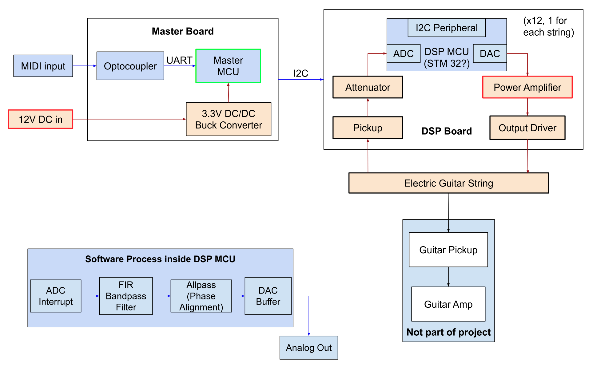 |
|||||